Install Guide – Incognito+
Device Provisioning
- The Incognito+ comes with a pre-installed SIM card and is provisioned on our GPS tracking platform.
- Each device is checked for connectivity prior to being delivered to a client site.
- The device is not IP67 rated, so be cautious
when installing it in the engine bay or in an exposed location.
Warning: Do not disassemble the device, If the device is
damaged, the power supply cables are not isolated or the isolation is damaged,
DO NOT touch the device before unplugging the power supply.
Installation Tips
- Standard installation is the connection of:
- Power
- Ground
- Ignition source
- This device can be mounted on the asset to be tracked using screws, bolts, cable ties or industrial adhesives.
- Mounting the device in a horizontal orientation
with the label side facing up is recommended.
- Do not mount under metal objects.
- The device should be mounted as far away from the radio and speakers as possible.
- Connecting Wires:
- Wires should be connected while the module is
not plugged in.
- Wires should be fastened to stable wires or
non-moving parts. Any heat omitting and/or moving objects should be kept away
from wires.
- There should be no exposed wires. If factory
isolation was removed while connecting wires, the isolation material should be
applied
- If wires are placed in the
exterior or in places where they can be damaged or exposed to heat, humidity,
dirt etc. additional isolation should be applied, and the wires should not be
loose.
- Connecting Power Source:
- After the car computer goes to sleep mode, power
might be still available on the power wires. Depending on the car model, this
may happen in 5-30 minutes period.
- When the module is connected, measure the
voltage again to make sure it did not decrease.
- It is recommended to connect to the main power
cable in the fuse box.
- 3A, 125 V external fuse to
be used.
- Connecting Ignition Wire:
- Check if it is a real ignition wire i.e. power
does not disappear after starting the engine.
- Check if this is not an ACC wire (when the key
is in the first position, most of the vehicle electronics are available).
- Check if power is still available when you turn
off any of the vehicle device.
- Ignition is connected to
the ignition relay output. As alternative, any other relay which has power
output when ignition is on, may be chosen.
- Connecting Ground Wire:
- Ground wire is connected to the vehicle frame or
metal parts that are fixed to the frame.
- If the wire is fixed with
the bolt, the loop must be connected to the end wire.
Note: If the device is not securely mounted to
the vehicle then it may trigger false accident/rollover alerts and harsh
driving events.
Additional Components
Buzzer/LED Indicator
- Connect one terminal to a positive power source (red wire)
- Connect the other terminal (black wire) to the PURPLE Digital Output 1
- The Buzzer/LED indicator is IP67 rated, and should be installed correctly using the supplied rubber grommet.
Note: Either terminal can be used for power or ground.
Driver ID
- Connect driver ID reader’s RED and WHITE wires to vehicle ground source.
- Connect driver ID reader’s GREEN wire to Incognito+’s GREEN wire.
- Connect driver ID reader’s BLACK wire to Incognito+’s BLUE wire.
- Connect Incognito’s ORANGE/WHITE wire to buzzer’s negative pole (ORANGE/WHITE goes to the same pole with Incognito’s PURPLE wire)
Teltonika Driver ID Reader
1. Connect Green wire (Reader) to vehicle Ground source.
2. Connect White wire (Reader) to device Green wire.
3. Connect Brown wire (Reader) to vehicle Power source
Immobilisation Wiring
The Incognito+ includes three switched ground output wires (DOUT), orange/white (DOUT1), purple (DOUT2) and dark grey (DOUT3).
These should be used with a RELAY. The DOUT wire controls the NEGATIVE side of the relay coil (PIN 86). The DOUT wire supplies ground to turn the coil on (energise) and goes high impedance to turn the coil off (de-energise).
NOTE: Please confirm with one of the Fleetware team around which Digital Output wire should be used prior to installation.
Step 1.
Connect the relay coil positive (PIN 85) to the vehicle's +ve (12/24V). Connect the relay coil negative (PIN 86) to the Incognito+ DOUT wire.
The relay has normally open (PIN 87) and normally closed (PIN 87A) contacts. The common connection is PIN 30.
Step 2.
If the vehicle will only be remotely immobilised (from Trackd or Pulse GPS for example), use PIN87A and PIN30 to control the starter motor. This is to save power by not energising the coil permanently.
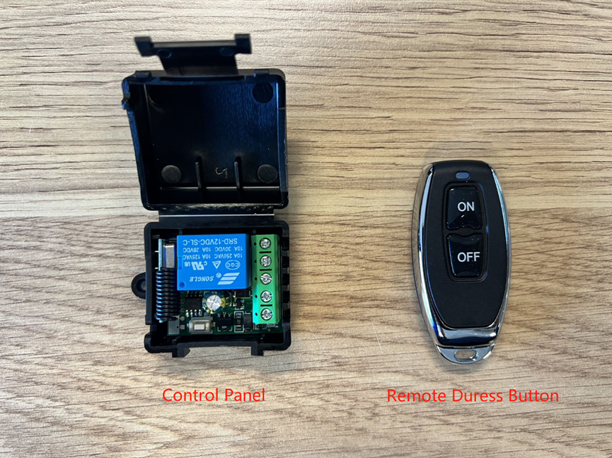
Remote Duress Button
(1) Connect A+ port on the control panel to the positive pole of power supply
(2) Connect A- port on the control panel to the negative pole of power supply
(3) Connect NO port on the control panel to the positive pole of power supply
(4) Connect DIN3 (White) wire from Incognito+ device to the COM port of the control panel
Wiring Harness
Note: Please refer to the vehicle or asset wiring information before wiring the device, to ensure that the correct wires are being connected.
LED Indicator
Device Testing
On completion of the installation, please contact us on 1300 88 36 79 to allow us to check that the device is correctly functioning.
Please have the device IMEI number (printed on the device) and Customer Name ready.
Related Articles
Install Guide – Incognito
Device Provisioning The Incognito comes with a pre-installed SIM card and is provisioned on our GPS tracking platform. Each device is checked for connectivity prior to being delivered to a client site. The device is not IP67 rated, so be cautious ...Install Guide – DU-BLE Angle Sensor for Agitator Trucks
Device Provisioning This device comes pre-configured and paired to one of our FMM130 Incognito telematics devices and is provisioned on our GPS tracking platform. Each device is checked for connectivity prior to being delivered to a client site. ...Install Guide – Remote Worker
Device Provisioning The Remote Worker comes with a pre-installed SIM card and is provisioned on our GPS tracking platform. Each device is checked for connectivity prior to being delivered to a client site. The device is not IP67 rated, so be cautious ...Install Guide – Rugged Tablet
Device Provisioning The Rugged Tablet comes pre-installed with the relevant applications as per the customer requirements. The Rugged Tablet comes pre-configured to use the Accessory line of a vehicle to power and shutdown the tablet while in the ...Install Guide – Dash 4G
Device Provisioning The Dash 4G comes with a pre-installed SIM card and is provisioned on our GPS tracking platform. Each device is checked for connectivity prior to being delivered to a client site. The device is not IP67 rated, so be cautious when ...