Install Guide – Remote Worker V2.0
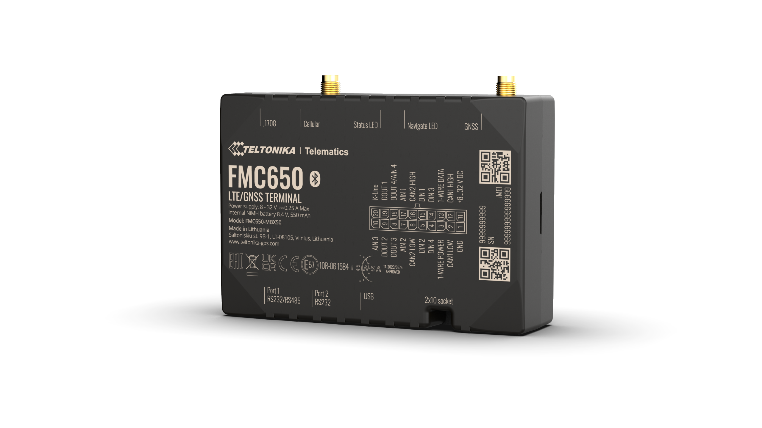
Device Provisioning
- The Remote Worker comes with a pre-installed SIM card and is provisioned on our GPS tracking platform.
- Each device is checked for connectivity prior to being delivered to a client site.
- The device is not IP67 rated, so be cautious
when installing it in the engine bay or in an exposed location.
- The device is delivered with an Iridium
satellite modem that will be plugged into the Remote Worker using the separate connector cable supplied.
- The device is delivered with a momentary Duress Switch that will be connected to the Remote Worker’s wiring harness.
Warning: Do not disassemble the device, If the device is
damaged, the power supply cables are not isolated or the isolation is damaged,
DO NOT touch the device before unplugging the power supply.
Installation Tips
- Standard installation is the connection of:
- Power
- Ground
- Ignition source
- Momentary Duress Switch (Green/White)
- This device can be mounted on the asset to be tracked using screws, bolts, cable ties or industrial adhesives.
- Mounting the device in a horizontal orientation
with the label side facing down is recommended.
- Do not mount under metal objects.
- The device should be mounted as far away from the radio and speakers as possible.
Note: If the device is not securely mounted to the vehicle then it may trigger false accident/rollover alerts and harsh driving events.
- Connecting Wires:
- Wires should be connected while the module is
not plugged in.
- Wires should be fastened to stable wires or
non-moving parts. Any heat omitting and/or moving objects should be kept away
from wires.
- There should be no exposed wires. If factory
isolation was removed while connecting wires, the isolation material should be
applied
- If wires are placed in the
exterior or in places where they can be damaged or exposed to heat, humidity,
dirt etc. additional isolation should be applied, and the wires should not be
loose.
- Connecting Power Source:
- After the vehicle computer goes to sleep mode, power
might be still available on the power wires. Depending on the vehicle, this
may happen in 5-30 minutes period.
- When the module is connected, measure the
voltage again to make sure it did not decrease.
- It is recommended to connect to the main power
cable in the fuse box.
- 3A, 125 V external fuse to
be used.
- Connecting Ignition Wire:
- Check if it is a real ignition wire i.e. power
does not disappear after starting the engine.
- Check if this is not an ACC wire (when the key
is in the first position, most of the vehicle electronics are available).
- Check if power is still available when you turn
off any of the vehicle device.
- Ignition is connected to
the ignition relay output. As alternative, any other relay which has power
output when ignition is on, may be chosen.
- Connecting Ground Wire:
- Ground wire is connected to the vehicle frame or
metal parts that are fixed to the frame.
- If the wire is fixed with
the bolt, the loop must be connected to the end wire.
- For better contact scrub paint from the spot where loop is going to be connected.
- Connecting Antennas
- Gently connect antennas to device by hands, without using additional equipment like pliers. The tightening torque for fixing the connector must be up to 0.5 – 0.7 Nm (‘hand tightened’).
- When placing antennas avoid easily reached places.
- Avoid GNSS antenna placement under metal surfaces.
- GNSS antenna must be placed so its state is as horizontal as possible (if antenna is leant more than 30 degrees, it is considered incorrect mounting).
- GNSS antenna cable cannot be bent more than 80 degrees.
- GNSS antenna must be placed sticker facing down.
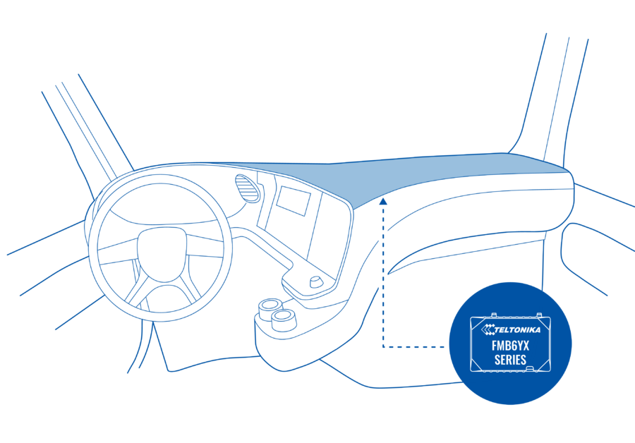
- It is recommended to place GNSS antenna behind dashboard as close to the window as possible. A good example of GNSS antenna placement is displayed in a picture below (area coloured blue):
- Connecting Iridium Modem:
- The device is delivered with an Iridium
satellite modem that will be plugged into the Remote Worker using the provided connector cable plugged into COM Port 1.
- There are several loose cables coming out of the connector cable. The GREY cable is for power to the Iridium modem and should be connected to the same power source as the wiring harness. The BROWN cable is for ground to the Iridium modem and should be connected to the same or similar grounding point as the wiring harness. The RED cable is for the power status of the Iridium modem which should be connected to the analogue input 1 (PIN17)(GREY) wire from the device. The BLUE cable is for the network status of the Iridium modem which should be connected to the analogue input 2 (PIN7)(BLUE/WHITE) wire from the device.
IMPORTANT: Please ensure that the Iridium satellite modem is mounted in a location that provides a clear unobstructed 360 degrees view of the sky in all directions. Typically, a suitable mounting location is in the middle of the vehicle dashboard or on top of an asset.
- Connecting Duress Switch:
- Connect the RED wire from the duress button to the power source.
- Connect the black wire to the device GREEN/WHITE wire.
Test these devices thoroughly as it is crucial
that they are functioning properly.
Note: Please note the switch must be held in the on
position for 3 seconds to activate.
Additional Components
Buzzer/LED Indicator
- Connect one terminal to a positive power source (red wire)
- Connect the other terminal (black wire) to the PURPLE Digital Output 1
- The Buzzer/LED indicator is IP67 rated, and should be installed correctly using the supplied rubber grommet.
Note: Either terminal can be used for power or ground.
Driver ID
- Connect driver ID reader’s RED and WHITE wires to vehicle ground source.
- Connect driver ID reader’s GREEN wire to Remote Worker’s GREEN wire.
- Connect driver ID reader’s BLACK wire to Remote Worker’s BLUE wire.
- Connect Remote Worker’s ORANGE/WHITE wire to buzzer’s negative pole (ORANGE/WHITE goes to the same pole with Remote Worker’s PURPLE wire)
Teltonika Driver ID Reader
1. Connect Green wire (Reader) to vehicle Ground source.
2. Connect White wire (Reader) to device Green wire.
3. Connect Brown wire (Reader) to vehicle Power source
CAN Adapter
- Be ready with a vehicle connection scheme that you have received from vehicle manufacturer or representative.
- Check the scheme for the current vehicle connection. Look for connectors matching PINs numbers and colours (may be different) according to connection scheme.
- Connect CAN adapter with Remote Worker:
- Connect CAN adapter's MINI USB to USB of Remote Worker.
- Connect CAN adapter CAN wires (CAN L, CAN H) as specified in connection scheme.
- Connect CAN adapter positive and ground wires to the vehicle power supply lines or near Remote Worker power wires.
- Switch vehicle ignition to ACC position. CAN adapter LED diode on the back should start blinking.
- Configure CAN adapter to read CAN bus data or control vehicle by setting its program number:
- Contact your Fleetware Sales Representative or Fleetware Support and provide the vehicle make, model and year to obtain the program number.
- The Fleetware Team will then set the program number remotely and confirm once completed.
Do not swap CAN L and CAN H lines. Not all CAN adapter wires may be used in vehicle.
Do not swap power supply lines. Make sure that voltage does not exceed 30V.
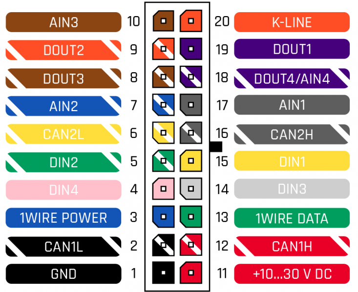
If you are having trouble finding the CAN line for the vehicle, please consult the vehicle manual or use the OBD-II standard as noted in the pinout diagram below.
Wiring Harness
Pin Number | Colour | Pin Name | Description |
1 | Black | Ground | Ground |
2 | Black/White | CAN1L | SAE J1939 CAN interface Low channel 1 |
| 3 | Blue | 1 Wire Power | Power supply pin for Dallas 1-Wire® devices |
4 | Pink | Digital Input 4 | Digital input, channel 4 |
5 | Green/White | Digital Input 2 | Digital input, channel 2 |
6 | Yellow/White | CAN2L | SAE J1939 CAN interface Low channel 2 |
7 | Blue/White | Analog Input 2 | Analog input, channel 2. Input range: 0-30V/0-10V DC |
8 | Brown/White | Digital Output 3 | Digital output. Open collector output |
9 | Orange/White | Digital Output 2 | Digital output. Open collector output |
10 | Brown | Analog Input 3 | Analog input, channel 3. Input range: 0-30V/0-10V DC |
11 | Red | Power | Power supply (+12-24 V DC) |
12 | Red/White | CAN1H | SAE J1939 CAN interface High channel 1 |
13 | Green | 1 Wire Data | Data channel for Dallas 1-Wire® devices |
14 | White | Digital Input 3 | Digital input, channel 3 |
15 | Yellow | Digital Input 1 | Digital input, channel 1. DEDICATED FOR IGNITION INPUT |
16 | Dark Grey/White | CAN2H | SAE J1939 CAN interface High channel 2 |
17 | Dark Grey | Analog Input 1 | Analog input, channel 1. Input range: 0-30V/0-10V DC |
18 | Purple/White | Digital Output 4 / Analog Input 4 | Digital output. Open collector output OR Analog input, channel 4. Input range: 0-30V/0-10V DC |
19 | Purple | Digital Output 1 | Digital output. Open collector output |
20 | Orange | K-LINE | K-LINE interface for online Tachograph Vehicle Data transfer |
Note: Please refer to the vehicle or asset wiring information before wiring the device, to ensure that the correct wires are being connected.
Led Indicator
Connecting to Other Devices
- It is possible to connect the AD Plus camera to our Remote Worker (V2) solution to allow for limited information on critical events
triggered on the AD Plus to be sent via the satellite Iridium network when
outside of cellular coverage. This can be achieved by connecting the SENSOR OUT 1 (YELLOW/WHITE) line from the AD Plus (via it's optional Datahub) to the DIGITAL INPUT 3 (WHITE) line on
the Remote Worker (V2) solution, as shown in the below diagram:
Device Testing
On completion of the installation, please contact us on 1300 88 36 79 to allow us to check that the device is correctly functioning.
Please have the device IMEI number or Serial number (printed on the device) and Customer Name ready.
Related Articles
Install Guide – Remote Worker
Device Provisioning The Remote Worker comes with a pre-installed SIM card and is provisioned on our GPS tracking platform. Each device is checked for connectivity prior to being delivered to a client site. The device is not IP67 rated, so be cautious ...User Guide – Portable IVMS/Remote Worker V2.0
Device Provisioning The Portable IVMS comes with a pre-installed SIM card and is provisioned on our GPS tracking platform. Each device is checked for connectivity prior to being delivered to a client site. The device is IP67 rated only while enclosed ...Install Guide – AD Plus V2
Device Provisioning The AD Plus V2 comes with a pre-installed SIM card and is provisioned on our GPS tracking platform, and video monitoring platform. The AD Plus V2 also come pre-installed with SD Card(s) for on-board video recording. Each device is ...Install Guide – AD Plus
Device Provisioning The AD Plus comes with a pre-installed SIM card and is provisioned on our GPS tracking platform, and video monitoring platform. The AD Plus also come pre-installed with SD Card(s) for on-board video recording. Each device is ...Install Guide – Incognito+
Device Provisioning The Incognito+ comes with a pre-installed SIM card and is provisioned on our GPS tracking platform. Each device is checked for connectivity prior to being delivered to a client site. The device is not IP67 rated, so be cautious ...