Install Guide – AD Plus
Device Provisioning
- The AD Plus comes with a pre-installed SIM card and is provisioned on our GPS tracking platform, and video monitoring platform.
- The AD Plus also come pre-installed with SD Card(s) for on-board video recording.
- Each device is checked for connectivity prior to being delivered to a client site.
- The only adjustment to the camera that is required during installation is the setting of the camera angles for each specific vehicle type.
Installation Tips
Selecting Camera Placement
Requirements for installation area of AD Plus:
1. The AD Plus must be installed in the middle of the front windshield, generally in the rear-view mirror area above the centreline of the front windshield. If this is impossible, the leftward or rightward deviation of the installation position shall not exceed 40cm (the leftward or rightward deviation of the AD Plus relative to the centreline of the front windshield is calculated with the centreline of the forward-facing camera lens as an index).
2. The external camera lens of the AD Plus must be located within the working range of the left and right windshield wipers as required (make sure that the screen of the external camera lens is clean and free from stains).
The installation position shall be determined in such a way that the AD Plus will not hinder the driver from viewing the front blind spot reflector, and there is no obstruction (such as interior rear-view mirror or glass coating) within the field of view in front of and around the internal and external cameras lens.
Preparing the Installation Area
- Quick pre-clean of interior and exterior of installation area for tough spots if necessary
- Use a wet disposable towel or cloth (light colours preferred to show contaminant removal)
- Final clean of installation area with the provided alcohol wipe
- Clean before priming (see above)
- Apply primer across installation area
- Let dry before applying tape
Installing the Camera Bracket
Ensure the toothed side of the bracket is facing left.

Wiring Connection
- Power Supply
- Connect the RED WIRE to a vehicle positive source (+).
- Connect the BLACK WIRE to a vehicle negative source (-).
- Connect the ORANGE WIRE to a vehicle ignition source (+).
- Indicator Signals
- After locating the fuse board below the steering
wheel or the front passenger dashboard, measure the cable corresponding to indicator/reversing
signal according to the tips on the cover back of the fuse board or using a
multimeter.
- For the standard hardwire, there are only two IO
signal cables, so only connection to the left and right steering signals
respectively is required.
- Connect Power Supply to AD Plus
- Plug the basic interface line into the short
cable coming out of the Power Supply Box / Datahub. It will only fit into one of the short
cables.
- Then, connect the long cable from the Power
Supply Box / Datahub to the long cable coming from the AD Plus camera.
- Slide the included heat shrink over the area where the two cables connect, and heat gently until the heat shrink forms a tight cover across the cables.
- Positioning the Power Supply Box / Datahub
- The AD Plus is equipped with a power supply box / datahub which has an in-built switch control. Therefore, the power supply box / datahub needs to
be fixed on an accessible position in the vehicle. Please pay attention to the
following tips when choosing the fixed position:
- Close to OBD interface or power
ports of hardwiring
- Horizontal surface mounting
- No interference with other
components
- Away from vibrating and
jittering positions, such as trumps and motors
- Hidden
positions preferred
- Connecting the Seat Vibration Unit
- The Seat Vibrator is powered via a Power Supply Box as shown below:
- The Power Supply Box should be connected to the same power supply as the Datahub, by connecting the cables labelled 7 as below:
- Connect the RED WIRE to a vehicle positive source (+).
- Connect the BLACK WIRE to a vehicle negative source (-).
- Connect the YELLOW WIRE to the SENSOR OUT2 wire from the Datahub Sensor port (both labelled 8).
- Connect the red and black cable (shown below) to the Power Supply Box by connecting the ends labelled 6:
- Then, connect the red and black cable to the Seat Vibrator with the end labelled 10:

Installing the Camera
Wiring Harness
Connection diagram
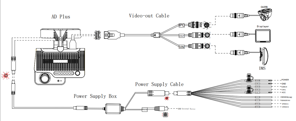
Basic interface
Video output interface
Calibration
IOS (Apple Store) |
Android (Google Store) |

Connecting the App
ADAS Calibration
- Measuring the height of the ADAS Lens
- Use a tower ruler or tape measure to measure the
vertical height (accurate to cm/inch) from the ground to the AD Plus front-view
lens as the installation height of ADAS lens:
- Calibration of ADAS Lens
- In the Veyes App, click [Preview] > [AI
Calibration]:
- Then click the ADAS button:
- Ensure Channel 1 is selected and then
click the Calibration button in the bottom right:
- Check the two checkboxes to confirm that the AD
Plus has been installed correctly and click the Next button:
- Enter the measured horizontal ground clearance
of the front ADAS lens in CM or Inches and click the Next button:
- Click Next (or you can click Learn more
to get additional information on ADAS calibration):
Check the checkbox to confirm if you have connected the vehicle signals, and then:
Select the source of the vehicle speed (Satellite, Pulse, OBD or ATrack)
Select the IO wires that have been connected to Left/Right indicators
Select the indicator signal type (Source Voltage, Source Pulse)
Click the Next button
On the next screen you can test the Left and Right indicators are triggering correctly when applied. Once you are satisfied that they are working correctly, click the Complete button:
Adjusting Angle of Cabin Camera
Click [Preview] on the operation interface of the Veyes App to enter the preview interface and double-click channel 2 to enlarge the cabin screen.
Open the card slot panel at the bottom of the AD Plus, and insert the L-shaped socket head wrench into the cabin camera angle adjustment hole to adjust the angle of the cabin camera lens.
Adjust the cabin camera lens to meet the following conditions:
The left and right centres of the cabin are in the centre of the screen;
The screen of the cabin is horizontal;
The steering wheel of the vehicle is displayed at the left/right lower corner of the screen.
The final cabin camera preview should look similar to the below:
DMS Camera
DMS Camera Placement
- The DMS camera shall be installed on the A-pillar on the driver's side,
with the side facing the driver's face.
- The DMS camera lens shall be 80-110 cm away from the driver's face.
- The installation height of the DMS camera on the A-pillar shall be flush with the driver's face.
- Adjust the angle of the DMS camera up and down, and left and right, to ensure that the driver's face appears in the middle of the video screen and the lower edge of the screen is below the driver's chest.
- Make sure that the fill light of the DMS camera faces toward the driver's face (the fill light shall not face toward the seat belt; otherwise, it will lead to overexposure of video).
- Make sure that there is no other object (such as steering wheel) in the DMS video screen that will block the driver's face and the seat belt features.
- In the event of installation on A-pillar, the labelling surface of the DMS camera must face toward the A-pillar (with the arc side facing toward the driver).
- In the event of installation on dashboard, the labelling side of the DMS camera must face down (with the arc side up).
- After angle adjustment and calibration, the protective film on the DMS camera must be torn off, and the DMS camera must be locked with a socket head wrench to avoid shaking up and down, and left and right.
Installation
- Connect the end of the cable from the DMS Camera to the "VIN" port on the Video-Out cable.
- Connect the Video-Out cable to the top port of the AD Plus camera unit.
- Power on the AD Plus, and connect to the Veyes App.
- Enter the real-time preview screen, and first check whether the image from the DMS Camera is the correct orientation while at the target installation position:
- If the orientation is incorrect and the image is upside down, click [Preferences], [Surveillance] and [Image Setup] in sequence, and then select corresponding channel of the DMS camera. Then select the corresponding installation position at "Install Pos":
- In the event of installation on the left A-pillar, select "Left A-pillar".
- In the event of installation on the right A-pillar, select "Right A-pillar".
- In the event of horizontal installation on the dashboard, select "Dashboard".
- Once the correct installation position is achieved, first tighten the upper screw of the DMS camera mount (with the lower screw of the mount not tightened temporarily, so as to adjust the angle of the camera up and down):
- Adjust the left and right angle joints of the DMS camera through the hexagon socket screws, so as to adjust the angle of the DMS camera left and right:
- After adjusting the angle of the DMS camera up and down/left and right, make sure that the driver sits according to normal driving habits and posture, to meet the following conditions:
- Make sure that the driver's face appears in the middle of the video screen, and the lower edge of the screen is below the driver's chest.
- Make sure that the fill light of the DMS camera faces toward the driver's face (the fill light shall not face toward the seat belt; otherwise, it will lead to overexposure of video).
- Make sure that there is no other object (such as steering wheel) in the DMS video screen that will block the driver's face and the seat belt features.
- Tighten the lower screw of the DMS camera mount and the screws at the left and right angle joints to ensure that the camera will not shake up and down or left and right:
Calibration
- Login to the Veyes App
- Click [Preview] on the homepage to enter the preview interface, and double-click the driver channel to enter the main-stream full screen.
- Ensure the regular driver of the vehicle is sitting in the drivers seat in their regular posture, ensuring the driver's face appears in the middle of the screen and the lower edge of the screen is below the driver's chest.
- Click [AI Calibration] for calibration selection:
- Select [DMS] for calibration, and select the corresponding channel of the DMS camera (usually channel 3).
- Click [Calibration] to move on to the next step:
- Confirm the prompts and click [Next] to move on to the next step:
- Select [Front] or [Side] to determine the installation method of DMS camera. If the camera is installed on the A-pillar, select "Side" for side calibration.If the camera is installed right in the middle of the dashboard, select "Front" for front calibration:Ensure the correct option is selected that matches the installation position of the camera, otherwise the camera will be calibrated incorrectly.Note: Before clicking [Next] to start the formal calibration, ensure the driver is sitting in their normal driving posture and looking straight ahead.
- Click [Next] to move on to the next step for automatic face calibration. During calibration, make sure that the driver sits still according to normal driving habits and posture and looks straight ahead. In the process of side calibration, the intelligent algorithm will automatically learn the driver's head deflection angle and the positions of feature data of the driver's face.
- The driver sits still and waits for the equipment to be calibrated automatically. When the value of NUM reaches 301 in the mode of side installation and side calibration (51 in the mode of front installation and front calibration), the calibration frame turns to red from blue, and then the automatic calibration ends:
On-going Calibration:
Calibration Completed: - Click [Finish] to complete the calibration and exit the calibration mode.
Side BSD Camera
Side BSD Camera Placement
- The BSD camera is suitable for installation at the left/right tail of the vehicle body. The lens shall face forward and be installed at the height of 195 cm±15 cm to the ground.
- The BSD camera must be installed vertically.
- The installation position of BSD camera on the vehicle body shall be flat without any inclined arc surface, and be convenient for drilling and wiring.
- The side BSD camera can be installed on the left or right side of the vehicle body. Although the cameras used are of the same specification and model, they can be of different structures to match different sides of vehicle. As shown in the figure below, "B" is in the red circle of the label, indicating that the camera is installed on the right side, and "A" is in the red circle of the label, indicating that the camera is installed on the left side:
- The BSD camera consists of two parts: lens and fill light. The camera must be assembled with the lens at the upper part and the fill light at the lower part, regardless of left or right camera. Moreover, the photosensitive side of the fill light must face down:
- During installation of the BSD camera, the BSD camera base can first be installed with the round hole at the upper part and the waist hole at the lower part (so as to facilitate adjustment left and right, and thus ensure the vertical installation of BSD):
Installation
- Park the vehicle on the flat ground.
- At the selected installation position, drill the first hole with a 2.8mm drill bit, and then properly fix the camera mount. Make sure that the round hole is at the upper part and the waist hole at the lower part, as shown below:
- Align the mount with a level, and drill the remaining three screw holes. At the same time, drill a tail harness inlet hole for the camera at the appropriate position with an 18mm tapper, and then apply glass sealant to the screw holes on the vehicle body. Finally, tighten the mount screws, as shown below:
- Fix the camera on the mount (first apply excessive glass sealant to the inlet hole), and measure the installation height of the lens, as shown below:
Calibration
- Measure the distance between the point of the BSD camera lens relative to the ground and the vehicle head and the installation height of the camera (i.e. height from the camera lens to the ground, accurate to cm) as below:
- Login to the Veyes App.
- Click [Preferences], [Basic Setup], [Other Setup], [Algorithm], [BSD calibration settings] in sequence, and then enter the following two values: distance between the point of the BSD camera lens relative to the ground and the vehicle head, and installation height of BSD camera:
- Place a marker close to the side of the vehicle and 2m in front of the vehicle head, as shown below:
- Click [Preview] on the homepage to enter the preview interface, and double-click the BSD Camera channel to enter the main-stream full screen:
- On the preview interface, click [AI Calibration] and select [BSD], as shown below:
- Select the left or right BSD to be calibrated, and enter the real-time preview screen. Here, take the right BSD as an example:
- On the real-time preview screen of BSD, click [Calibration] at the bottom of the real-time screen, At this point, a red vertical line, a yellow horizontally inclined line and a yellow box appear on the screen, and "Up", "Down", "Left" and "Right" buttons appear on the left side of the screen:
- Click the "Left" and Right" buttons on the left side of the screen to move the "red vertical line" in the real-time screen until it just fits the edge of the vehicle body, and then click the "Up" and "Down" buttons to move the "yellow inclined line" in the real-time screen until it just coincides with the mark point on the ground at 2m away from the vehicle. (As shown above, the "vertical red line" coincides with the edge of the vehicle in the screen, while the "inclined yellow line" coincides with the traffic cone mark point on the ground at 2m away from the vehicle.)Confirm that the "red vertical line" and the "yellow inclined line" fit corresponding edges well, and then click [Save].
- At this point, the BSD calibration ends, and the alarm speed threshold can be changed to 0 to test the alarm trigger.
Connecting to Other Devices
Remote Worker (V1)
Remote Worker (V2)
Device Testing

Related Articles
Install Guide – AD Plus V2
Device Provisioning The AD Plus V2 comes with a pre-installed SIM card and is provisioned on our GPS tracking platform, and video monitoring platform. The AD Plus V2 also come pre-installed with SD Card(s) for on-board video recording. Each device is ...Install Guide – MDVR Solution
Device Provisioning The MDVR Solution comes with a pre-installed SIM card and is provisioned on our GPS tracking platform, and video monitoring platform. If you opted in for us to supply hard drive storage, this will come pre-installed on the MDVR ...Install Guide – MDVR Solution V2
Device Provisioning The MDVR Solution comes with a pre-installed SIM card and is provisioned on our GPS tracking platform, and video monitoring platform. If you opted in for us to supply hard drive storage, this will come pre-installed on the MDVR ...Install Guide – Remote Worker V2.0
Device Provisioning The Remote Worker comes with a pre-installed SIM card and is provisioned on our GPS tracking platform. Each device is checked for connectivity prior to being delivered to a client site. The device is not IP67 rated, so be cautious ...Install Guide – Remote Worker
Device Provisioning The Remote Worker comes with a pre-installed SIM card and is provisioned on our GPS tracking platform. Each device is checked for connectivity prior to being delivered to a client site. The device is not IP67 rated, so be cautious ...